The Premise
Our chassis house the remainder of the components required for our robot to succeed. In addition to it featuring the drive system, the chassis design took into consideration the placement of circuits, filtration systems, the on-vehicle computer, the arm and the containment. Taking these components into consideration allowed were pertinent in ensuring that our robot was able to successfully drive up the track, reach the agent holding tank, retrieve the agents with the arm and convoy them to the zipline.
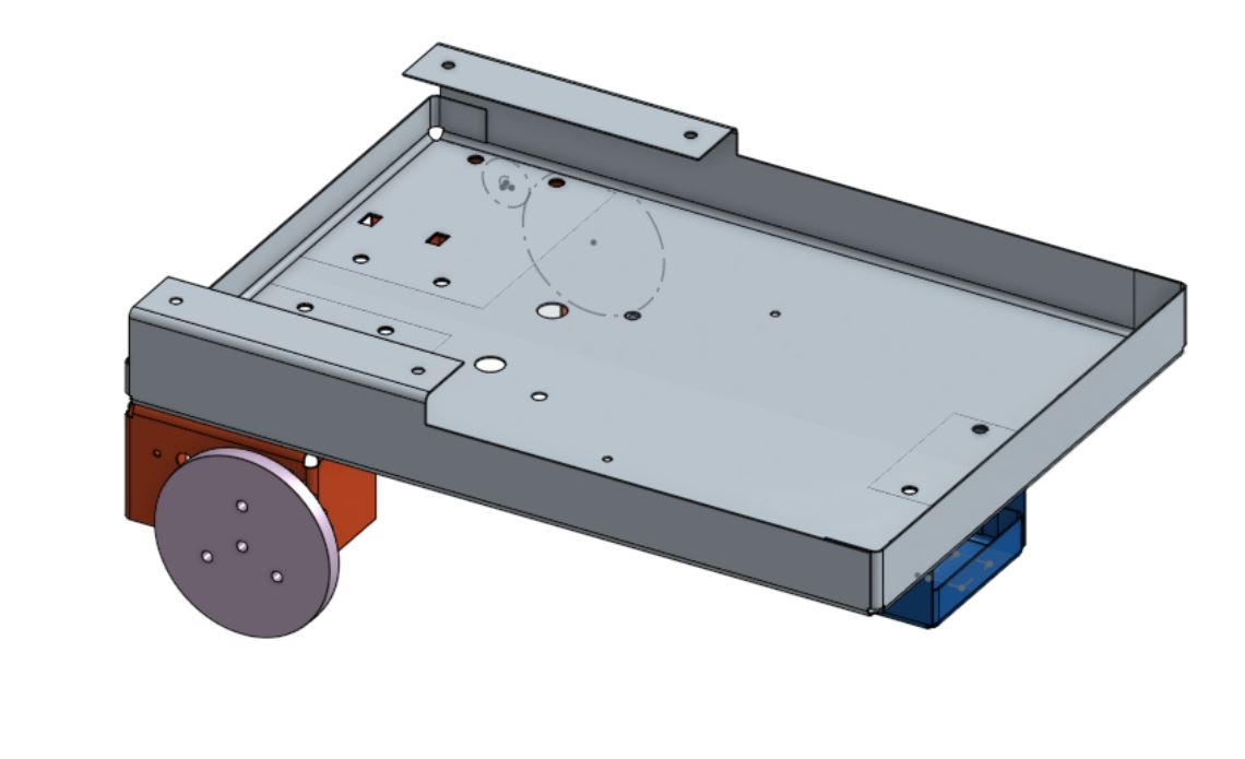
ALUMINIUM CHASSIS DESIGN
In out initial conception, we designed the chassis with a sheet metal model that featured a very box-like structure. Motors were placed beneath the main bay, with a QRD tape following system placed on a sled at the very front. Circuits, along with the main robot computer were placed at the front of the main bay, whilst the arm and elevator system along with the containment were placed in the back. Aluminum was chosen particularly because it presented a light weight alternative to steel and was easy to rapidly prototype. It's ability to be bent over hardboard was initially one major reason it was favored.
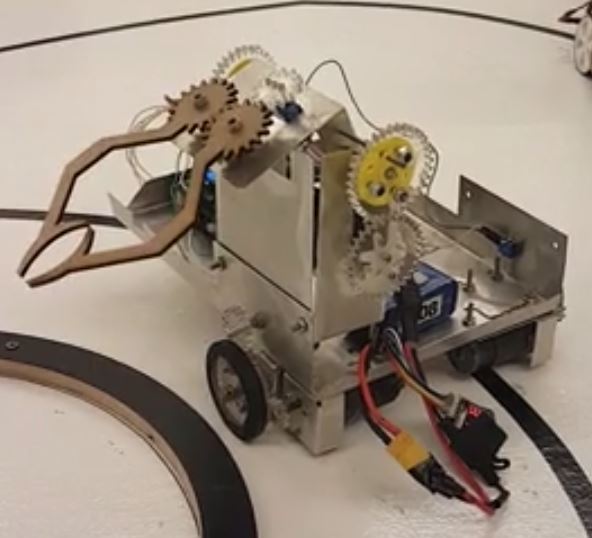
ALUMINIUM CHASSIS IMPLEMENTATION
After implementing the original design, we soon found many defects with the idea. Mainly, the aluminum design made our chassis a hotbed for short circuiting (and occasionally frying) our circuits. During debugging, many of our H-Bridges became defective, and our filtration system did not properly interpret signals. In addition to that, fabrication was more exhaustive as the waterjet finish of the chassis left edges that needed to be smoothed. Bends were not as exact as we had wanted, and while they did provide nice rounded corners, they often lead to coupling difficulties.
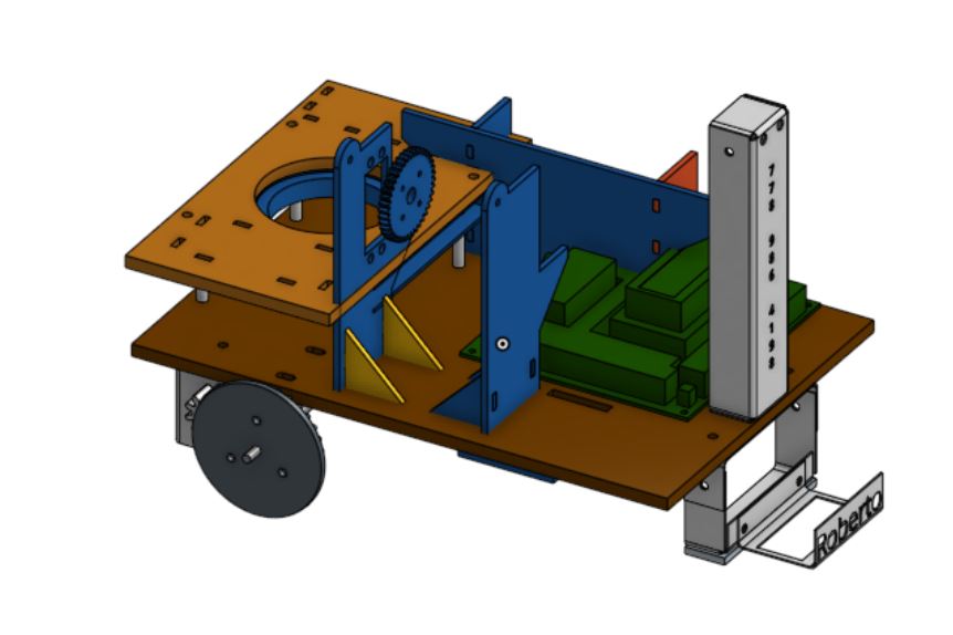
REITERATION OF DESIGN
Having learned about the pitfalls of alumninum, our second designw was based on hardboard and allowed for significanly easier fabrication. This concept allowed us to make the design more compact, giving us one of the smallest robots in the competition. Compactness was particularly helpful in driving and turning. One of the requirements of the competition was that our robot had to work on one of two possible surfaces: one that involved right hand turns and one that involved left hand turns (the surfaces were mirror images of each other). To facilitate this, our design used a lazy susan bearing driven platform ontop of which the arm would be situated. This allowed us to quickly turn and lock into place the arm for the corresponding track.
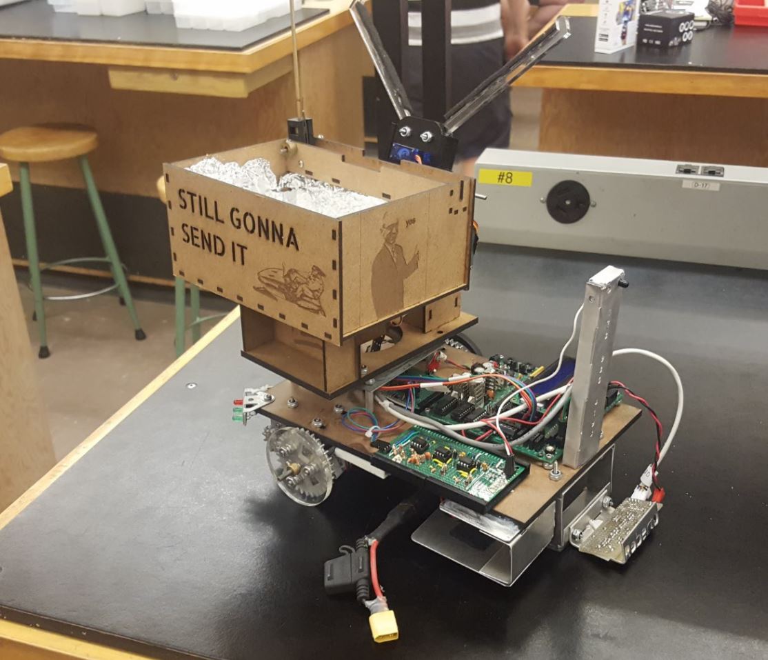
FINAL IMPLEMENTATION
The final implementation of our design was relatively consistent with the design we had for the hardboard based chassis. In departure from the metal-based chassis, we had fewer problems with shorting and frying circuits. H-Bridge circuits, along with the Coleman Barber geared motors we used were placed underneath the chassis. The IR filtration system, the TINAH Board and the power grid were placed at the front of the chassis. The lazy susan bearing was placed at the back half of the chassis, ontop of which the arm and the containment system were placed. One particular change from the design was that we opted to go with a hook mechanism to latch onto the zipline. This design change saw us no longer needing an elevator system for our robot.